
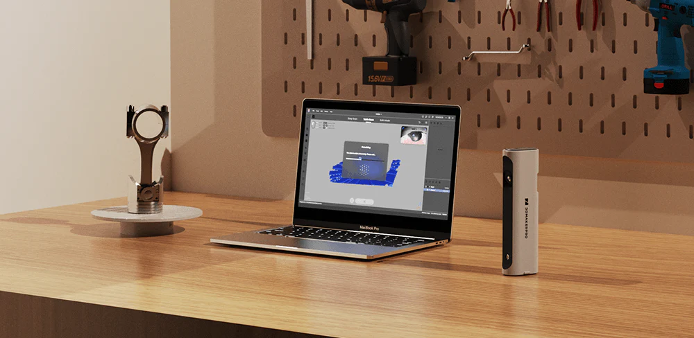
Using 3D printers nowadays can feel quite common but what matters is how to use them.
On the surface level, it seems quite easy: Scan, export, print, repeat. But behind this there are many issues that such printers encounter such as incomplete surfaces, unsuitable geometry and more!
This is why a reliable and trustworthy 3D scanner works out from capturte to fabrication.
Anyone researching a 3d scanner for 3d printer projects should assess the complete workflow instead of focusing only on accuracy figures.
Read further to know other details!
A 3D scanner measures visible surface details and represents the measurements as scan frames or point-cloud data. Processing software then aligns and fuses the data before generating a polygon mesh.
A typical process includes:
Each step affects the next. A clean scan reduces editing effort, while a repaired mesh is less likely to cause slicing errors. However, a complete digital model is not automatically ready. Thin sections, hidden cavities, uneven bases, and inaccurate holes may still require modification.
Good scan data begins with careful planning. Reflective, transparent, dark, or featureless surfaces can make optical tracking difficult. Repeated patterns and smooth cylindrical objects may also cause the scanner to lose its position.
Preparation may include:
The scanner should remain within its recommended working distance and move smoothly. Fast movement may create gaps, while repeatedly scanning the same area can produce unnecessary information.
Small objects may be easier to capture on a rotating stand. Larger objects usually require the operator to move around them. Each new viewing angle should overlap the previous capture so the software can align the data.
The three workflows follow the same general sequence, but their software environments and
export processes vary.
| Workflow | Processing Approach | Common Export Path | Practical Use |
| 3DMakerpro | JMStudio combines scanning, alignment, meshing, optimisation, and export | STL, OBJ, and PLY files can move into separate modelling or slicing software | Suitable for users who want a focused scan-to-mesh process |
| Creality | CrealityScan provides capture, alignment, meshing, smoothing, and hole filling | Processed models can transfer into compatible slicing software | Useful for users who already use Creality hardware or want to export processed scans into compatible slicing software |
| Revopoint | Revo Scan combines capture, editing, alignment, meshing, and model processing | Supports several mesh formats for modelling and slicing | Relevant for workflows requiring flexible export choices |
In practical terms, 3DMakerpro supports a direct scan-to-mesh workflow, Creality connects scanning more closely with a broader printing environment, and Revopoint provides several routes for exporting models into external editing or slicing tools.
No workflow is perfect for every project. A simple process may suit occasional object replication, while detailed editing controls may matter more for reverse engineering or product development.
Hardware also affects the outcome. Field of view, working distance, tracking method, intended object size, and computer requirements can influence usability as much as the software.
A raw scan may contain floating points, rough surfaces, holes, duplicate geometry, or parts of the surrounding table and environment. These elements should be removed before the model enters a slicer.
Alignment combines separate scanning passes into one coordinate framework. Poor alignment may produce doubled edges, softened details, or incorrect dimensions. The model should be inspected from several angles before the scans are fused.
Mesh simplification reduces the number of polygons in the file. This makes the model easier to edit and prepare, but excessive reduction can remove engravings, flatten curves, or soften edges.
The final mesh should normally define a closed shape. Gaps, reversed faces, intersecting surfaces, and zero-thickness areas can prevent the slicer from interpreting the model correctly. Automatic repair tools can fix small defects, although major missing areas may need manual reconstruction.
STL is widely used for 3D printing because it represents surface geometry through polygons. It does not normally preserve colour or texture details.
OBJ can store geometry and texture coordinates, while accompanying MTL and image files may be required to preserve the model’s full textured appearance, while PLY may store point clouds, meshes, and colour details. The 3MF format can include units, materials, and manufacturing data where supported.
The correct choice depends on what happens afterward. STL works well for basic slicing, while OBJ or PLY may be more useful when further modelling or visual data is required.
Units should always be checked during export and conversion. A mismatch between millimetres and another unit can cause the model to appear far too large or small.
A scan captures the object as it currently appears, including wear, dents, deformation, and manufacturing imperfections. A replacement part may therefore need more than simple mesh repair.
Common edits include flattening the base, correcting circular holes, restoring worn edges, increasing wall thickness, removing unnecessary internal geometry, or adding spacing between connected parts.
Critical measurements should be checked with suitable measuring instruments. A detailed mesh may still require dimensional adjustment before the printed part fits correctly.
Printing a small test section can help confirm holes, joints, and gaps before material is used on the complete model.
The slicer converts the repaired model into layers and printer commands. Layer height, wall count, infill, supports, temperature, and orientation all influence the final result.
Orientation is especially critical. Rotating the model can reduce supports, improve visible surfaces, and strengthen load-bearing areas.
Before printing, the sliced preview should be checked for missing walls, thin features, unsupported areas, internal cavities, and incorrect dimensions. A small test print can reveal fitting problems or lost detail before final production begins.
A successful scan-to-print workflow depends on more than the scanner’s advertised precision. Object preparation, stable tracking, complete surface coverage, mesh repair, dimensional editing, and slicing decisions all influence whether the finished model can be printed reliably.
The most suitable workflow is the one that supports the intended object size, editing needs, export format, and printing platform. Beginning with a simple object and producing a test print provides a practical way to evaluate the entire process before moving to more complex projects.
Ans: The latest Creality Scan 4 brings a completely redesigned interface, AI-powered features, and significantly faster performance.
Ans: Yes, all versions of our scanning software (Revo Scan, Revo Metro, Revo Trackit, and Revo MetroX) and support software like Revo Mirror are free and can be downloaded from the support section on our website.
Ans: The techniques work with most or all sensor types including optical, acoustic, laser scanning, radar, thermal, and seismic.
Ans: Photogrammetry is better for creating large-scale models., on the other hand, 3D laser scanning is best for capturing smaller objects with high accuracy and detail.
